
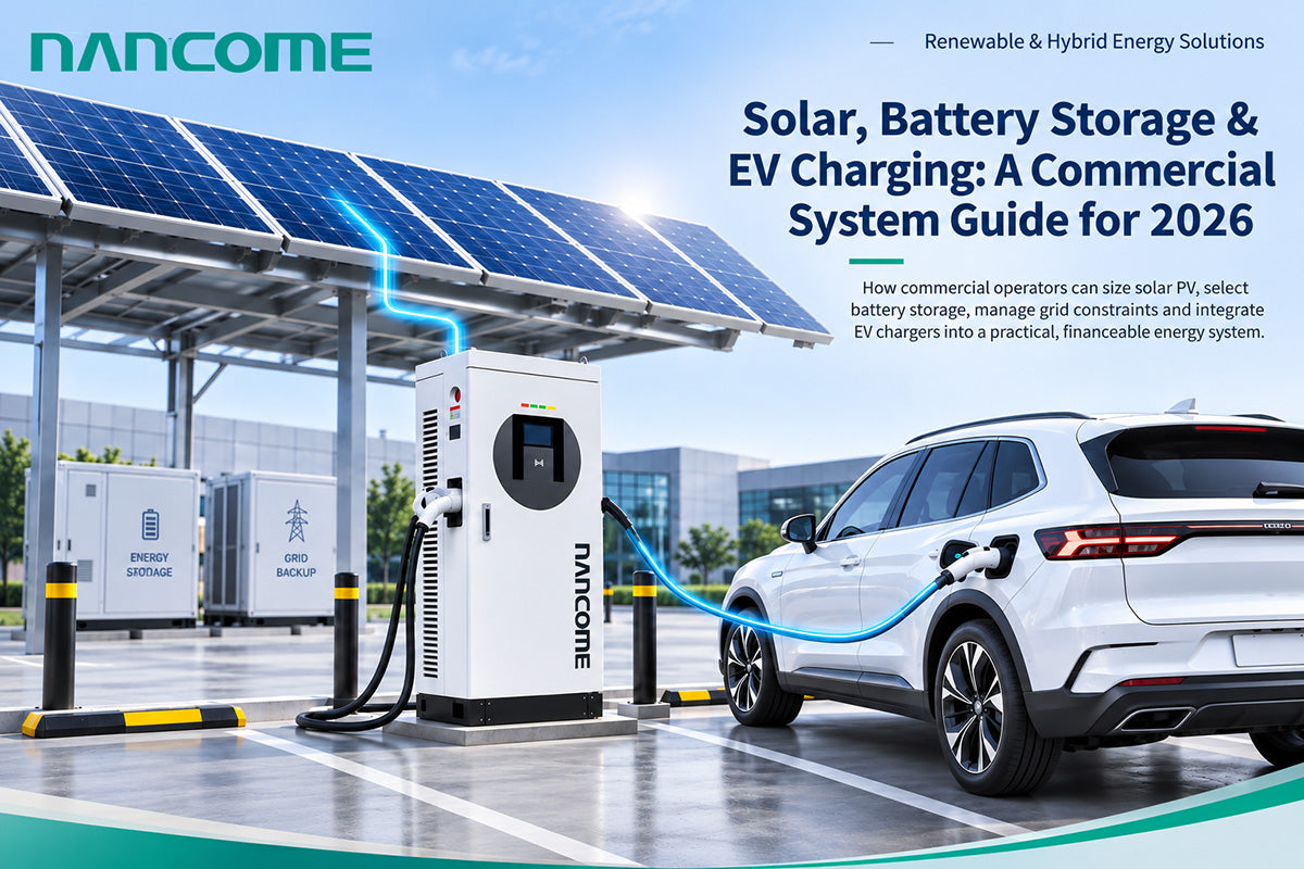
How commercial operators can size solar PV, select battery storage, manage grid constraints and integrate EV chargers into a practical, financeable energy system
A solar canopy does not make a charging station self-sufficient. A successful commercial solar-plus-storage EV charging project matches four things: the vehicles’ real charging schedule, the solar production profile, the battery’s usable power and energy, and the site’s permitted grid import.
This guide is for charging-point operators (CPOs), EPC contractors, distributors, commercial property owners, fleet managers and energy developers. It moves beyond the question of whether solar charging is attractive and explains how to specify an integrated system, avoid common sizing errors and prepare a credible RFQ. It also shows where NANCOME charging equipment and electrical distribution experience fit within a multi-vendor project.
2026 Market Snapshot: Why Integrated Charging Systems Matter
- The IEA reports that global public EV charging points exceeded 7 million at the end of 2025, after growth of more than 33% during the year. More charging points also mean more complex site-level power requirements. [1]
- Solar PV installations exceeded 600GW worldwide in 2025, while annual battery storage additions reached 108GW, up about 40% from 2024. These are global market indicators, not promises of project-level returns. [2][3]
- The IEA expects solar PV to account for almost 80% of global renewable capacity growth from 2025 to 2030, while curtailment and periods of low or negative wholesale prices increase the value of flexibility in some markets. [4]
- Electric trucks and higher-power charging are expanding, but charging infrastructure must still be designed around grid capacity, vehicle acceptance rates and operating schedules. [1]
Market figures are drawn from IEA publications available in 2026. Solar yield, tariffs, grid codes and business models must be assessed for each country and site; no single global return assumption is appropriate.
1. What Is a Commercial Solar + Battery Storage + EV Charging System?
A commercial solar EV charging system combines electricity generation, energy conversion, optional battery storage, electrical distribution and EV charging under coordinated controls. Most commercial projects remain grid-connected: the grid supplies power when solar generation is low and may absorb surplus PV where export is permitted. Battery storage can shift energy between time periods or support short power peaks, but it cannot create energy.
A typical AC-bus design is: PV modules → PV inverter → low-voltage distribution bus; grid → transformer and switchgear → the same bus; BESS → bidirectional PCS → the bus; and the bus → AC chargers or DC fast chargers → vehicles. An energy management system (EMS) supervises power limits and dispatch, while a charging station management system (CSMS) handles charging operations and customer workflows.
| System element | Primary role | Commercial design question |
|---|---|---|
| Solar PV array + inverter | Generate daytime AC energy | How much of the PV output can the site use or export? |
| Battery energy storage system (BESS) + PCS | Shift energy and/or supply peak power | What kW, usable kWh, cycle life and reserve are required? |
| Grid connection + transformer/switchgear | Supply reliable power and protect equipment | What import/export limits and protection rules apply? |
| EV chargers + connectors | Deliver controlled charging to vehicles | Which vehicles, dwell times, plugs and simultaneous loads? |
| EMS + charger/CSMS interfaces | Coordinate site import, PV, storage and charging | Which commands, meters, fail-safe limits and tests are supported? |
A key distinction: “solar-ready,” “battery-compatible” and “OCPP-supported” are not interchangeable certifications. An integrator must verify the exact power path, interface protocol, firmware, inverter/PCS controls and grid-protection scheme before promising a complete operating system.
2. Four Architectures Commercial Buyers Should Compare
| Architecture | Best-fit scenario | Key advantage | Main limitation |
|---|---|---|---|
| A. Grid + EV chargers | Sites with adequate utility capacity | Simple baseline and fewer integration layers | Exposure to grid tariffs and demand peaks |
| B. Grid + solar PV + chargers | Daytime workplace or destination charging | Offsets energy bought during solar hours | Solar alone rarely covers evening peaks |
| C. Grid + solar PV + BESS + chargers | Demand charges, time-of-use tariffs or grid constraints | Adds dispatch flexibility and peak support | Higher capex and control complexity |
| D. Islandable / off-grid PV + BESS + chargers | Remote, temporary or specialized sites | Can operate with limited grid access if engineered | Requires firm energy budget, islanding controls and reserves |
For many existing sites, an AC-coupled design is a practical retrofit route: PV, BESS and DC chargers connect through a common AC distribution system. DC-coupled designs may be attractive in selected new-build systems, but require detailed verification of shared DC-bus voltage, converters, protections and control responsibility. “DC-coupled solar plus storage” does not mean that any DC charger can accept raw solar-panel output. NANCOME has a separate guide comparing AC-coupled and DC-coupled EV charging architectures.
Recommendation: compare a grid-only baseline, a grid-plus-PV option and a PV-plus-BESS option using the same charging demand, tariff, site constraints and service-level requirements. The most sophisticated architecture is not automatically the most economical.
3. Start With the Charging Load, Not the Solar Panel Count
The most common design error is to select a large solar array or battery before understanding how the vehicles actually charge. A site with 500kWh of daily charging demand may need only modest peak power if vehicles stay overnight, or several hundred kilowatts if most charging happens during a one-hour delivery window.
- Collect at least 15-minute interval data for existing site loads and, where possible, charger-session timestamps. Record the worst simultaneous demand rather than simply adding nameplate ratings.
- Define vehicle classes, daily energy per vehicle, charging windows, arrival uncertainty, required departure state of charge and vehicle-specific maximum DC acceptance.
- Record existing building loads, transformer capacity, available three-phase or single-phase supply, power factor, site import/export limits and any utility demand-charge ratchet.
- Separate energy (kWh per day) from power (kW at a moment). Battery capacity is measured in kWh; PCS and charger output limits are measured in kW.
- Define service objectives: maximum queue time, fleet departure reliability, minimum charger availability and any backup duration requirement.
A fleet depot with predictable overnight charging may prioritize scheduling and a smaller battery. A highway service area with irregular 15-minute fast-charging peaks may prioritize high BESS discharge power and fast recovery between sessions. A shopping center with midday dwell time may use a greater share of PV directly.
4. How to Size Solar PV for an EV Charging Site
A first-pass solar calculation estimates annual or daily generation, but final sizing requires hourly or sub-hourly modeling with local irradiance, roof orientation, shading, temperature, soiling, inverter clipping, degradation and export limits.
Illustrative daily PV energy (kWh/day) ≈ PV array size (kWp) × equivalent full-sun hours (h/day) × performance ratio.
For example, a 180kWp PV array, 4.0 equivalent full-sun hours and a 0.78 performance ratio gives approximately 562kWh/day (180 × 4.0 × 0.78 = 561.6). This is an illustrative average AC-side PV yield, not a guarantee of 562kWh delivered to EV batteries every day. Weather, seasonal changes, curtailment, storage losses and charger losses all affect the final result.
Three practical questions are more important than maximum panel count: What proportion of generation coincides with charging or building demand? Can surplus be exported and at what price? If export is limited, is the battery large enough and available at the right hours to absorb otherwise-curtailed energy?
Solar carports may offer shade, land-use efficiency and brand value, but civil works, canopy clearance, wind/snow loading, drainage, fire access and vehicle impact protection can materially change their installed cost.
5. How to Size Battery Storage: kW, kWh and Recharge Time
Battery sizing has two independent dimensions. Discharge power (kW) is how much instantaneous support the battery/PCS can provide; usable energy (kWh) is how long that support can continue. A battery with high energy capacity but insufficient PCS output may fail to shave a short peak. A high-power battery with too little usable energy may run out before charging sessions end.
First-pass BESS discharge power (kW) ≈ maximum simultaneous site demand − allowed grid import − coincident PV contribution. Include auxiliary loads and control margins.
First-pass nominal BESS energy (kWh) ≥ required AC support energy (kWh) ÷ [usable state-of-charge window × discharge-path efficiency]. The result is a screening estimate, not a substitute for vendor-specific performance modeling.
The battery must then recharge. If the site needs 120kWh of AC discharge support and a 94% discharge-path efficiency, the battery uses roughly 128kWh internally. At a separate 94% charge-path efficiency, restoring that energy requires roughly 136kWh of input before auxiliary consumption. Recharging over three hours would need about 45kW of average input power, assuming the grid/PV has headroom at that time.
Also check maximum continuous C-rate, degradation at the expected cycle count, operating temperature, fire protection, end-of-life capacity, minimum SOC reserve and the financial cost of round-trip losses. If a site has repeated peaks with little time to recharge, simply adding battery kWh may not solve the problem.
6. Dynamic Load Management Is the Control Layer
An EMS can coordinate PV, battery dispatch and a site import ceiling, while the CSMS and chargers manage session authorization, metering, availability and the actual charging setpoints. Integration is site-specific: OCPP 1.6-J and OCPP 2.0.1 support different smart-charging capabilities, and the actual implemented features must be verified with the selected platform and charger firmware.
- Protect the grid limit first: enforce a hard import ceiling using a reliable point-of-common-coupling meter and local fallback logic.
- Allocate charger power by vehicle urgency: departure time, minimum energy target, fleet priority and charger/vehicle capability—not simply first-come, first-served.
- Use available solar generation when practical, while respecting battery SOC limits, export rules and vehicle demand.
- Dispatch BESS for specific economic or operational objectives: demand-charge peak shaving, tariff arbitrage, charging-queue support or resilience. These objectives can compete.
- Define a safe response to meter failure, EMS/CSMS communication loss, network outages and a low battery SOC. Chargers must not assume unrestricted power is available.
Example control hierarchy: electrical protection and utility limits → local site power controller → BESS/PV dispatch → charger power budgets → CSMS session and commercial functions. Control ownership and response times should be documented in the project integration matrix.
7. Worked Example: Two 120kW DC Chargers on a Limited Grid Connection
Consider a hypothetical commercial depot with two 120kW DC chargers, an available 100kW grid-import budget for charging after other facility loads, a proposed 180kWp PV array and a stationary BESS. The chargers can request up to 240kW in total, but the representative busy period creates a combined 200kW AC-side charging-system input demand for 90 minutes. Assume coincident PV generation of 20kW during this period.
| Illustrative input | Value | Interpretation |
|---|---|---|
| Installed DC charger rating | 2 × 120kW = 240kW | Nameplate capacity, not continuous site demand |
| Peak AC-side charging demand | 200kW for 1.5 hours | 300kWh supplied to charger AC inputs, before charger conversion losses |
| Available grid power | 100kW | Import budget available to the charging system |
| Coincident PV power | 20kW | Must be modeled by hour, not daily average |
| BESS discharge power needed | 200 − 100 − 20 = 80kW | At least 80kW at the applicable AC bus, before margin |
| BESS AC energy support | 80 × 1.5 = 120kWh | Peak support for the assumed 90-minute window |
| Nominal battery screening size | 120 ÷ (0.80 × 0.94) ≈ 160kWh | 200kWh nominal offers additional illustrative margin |
| Illustrative BESS PCS | 100kW AC | Subject to overload, ambient temperature and protection review |
Under these assumptions, a 200kWh nominal battery with an 80% usable SOC window and 94% discharge-path efficiency can deliver approximately 150kWh AC within that window. That covers the modeled 120kWh support event with a limited margin. It does not establish that this battery will survive repeated peaks, remain adequate after years of degradation or satisfy fire and interconnection requirements.
The 180kWp PV example produces about 562kWh/day under the assumed average conditions. That energy cannot simply be subtracted from a 200kW AC-side evening charging peak; only PV power actually available during the peak reduces instantaneous BESS discharge. Likewise, a battery that finishes the peak at low SOC must have enough subsequent PV or grid headroom to recharge before the next event.
Worked example is illustrative engineering arithmetic, not a NANCOME quotation, guaranteed system performance, site design or a claim that a NANCOME mobile energy storage charger can be connected directly as a grid-parallel stationary BESS.
8. Choose the Right EV Chargers for the Operating Model
Solar and storage cannot compensate for a charging system that does not fit the vehicle fleet. Charger selection should follow dwell time, daily energy, connector standard, duty cycle, number of simultaneous vehicles and the available electrical service.
| Site type | Typical charging approach | How NANCOME can be relevant |
|---|---|---|
| Hotel, workplace, destination parking | 7/11/22kW AC where vehicles remain parked for hours | Commercial AC chargers, OCPP options and distribution planning |
| Retail and public fast charging | 40–480kW-class floor-standing DC selected by dwell time and vehicle mix | DC fast chargers, connector choices and platform integration checks |
| Truck, logistics, port or mining depot | High-power charging with departure priorities and cable handling | 240–800kW heavy-duty solutions; dual-gun parallel charging for one compatible truck, optional liquid-cooled cables; project verification required |
| Grid-limited small commercial location | Moderate output and carefully checked input current | 35/42kW single-phase 220V floor-standing DC option for suitable electrical services; not an ordinary household socket load |
| Temporary or emergency charging | Deployable energy storage-supported DC charging | NANCOME mobile storage charging options; not automatically equivalent to stationary grid-tied BESS |
For truck projects, the vehicle must support the proposed inlet configuration and any simultaneous dual-gun strategy. Rated charger power, actual vehicle acceptance, connector thermal limits and battery temperature must all be verified. For every product category, confirm the exact model, input voltage, connector, OCPP version, firmware and project-specific certification scope.
9. What Drives ROI in a Solar-Storage Charging Project?
The financial case must compare total lifecycle cash flows, not just the solar energy price or the charger nameplate power. Revenue depends on delivered charging kWh, utilization, pricing and uptime. Energy costs depend on the time and quantity of grid purchases, demand charges, PV self-consumption, export compensation and battery losses. Costs include PV structures, BESS/PCS, transformers, switchgear, protection, civil works, permits, software, maintenance, financing and eventual battery replacement.
Illustrative solar value calculation: if the 180kWp PV system produces approximately 205MWh in a modeled year, 75% is consumed on-site and the avoided retail tariff is USD 0.16/kWh, the gross avoided purchase value is about USD 24,600/year. If the remaining 25% can be exported at USD 0.04/kWh, export revenue would be roughly USD 2,050/year. These are hypothetical prices and exclude costs, taxes, performance degradation and any export restrictions.
Illustrative peak-shaving value: at a USD 18/kW-month demand charge, a sustained 60kW reduction in the billed monthly peak would imply up to USD 12,960/year before battery costs. Actual savings may be smaller because of demand ratchets, seasonal peak variation, battery recharge peaks, control limits and overlap with PV savings. Do not count the same avoided grid kWh or peak reduction twice.
- Model 10–15 years of operating costs and revenues with tariff sensitivity, rather than using a single optimistic payback figure.
- Stress-test cloudy weeks, battery degradation, lower charger utilization, delayed grid approvals and unexpected maintenance.
- Compare at least three scenarios: grid-only, PV-only and PV+BESS. Add an alternative transformer/grid-upgrade scenario where relevant.
- Measure investment quality using project cash flow, NPV/IRR or payback together with operational metrics such as missed departures and peak import violations.
10. Electrical Engineering, Safety and Grid Compliance
A commercial integrated site is an electrical infrastructure project. The engineering scope must cover the point of common coupling, utility interconnection, transformer rating, low-voltage switchgear, protective coordination, cable sizing, earthing/grounding, isolation, metering, surge protection, power quality and emergency shutdown. PV inverters and BESS PCS must be compatible with the local grid code and approved protection settings.
Battery safety requirements vary by jurisdiction and technology. Local authorities may require specific fire separation, ventilation, thermal-runaway mitigation, emergency response plans and applicable product/system standards. Requirements such as UL 9540/9540A or NFPA 855 may be relevant in certain US projects; other markets use different rules. These references describe possible project requirements, not claimed NANCOME certifications.
If backup or islanded operation is required, the project needs deliberate islanding detection, transfer arrangements, black-start capability where applicable, grid-forming control and a defined critical-load panel. A standard grid-following PV inverter or grid-connected battery does not automatically power DC chargers during a utility outage.
NANCOME’s background in power distribution and switchgear assembly is relevant to cabinet construction, component selection, wiring quality and system interface discipline. However, local licensed engineers and the EPC remain responsible for final site design, permitting and utility approval.
11. Factory Acceptance Testing and On-Site Commissioning
A successful factory test should verify the purchased configuration rather than only show that a charger can start one session. The commissioning plan should define responsibilities among the charger manufacturer, BESS/PCS supplier, PV inverter supplier, EMS vendor, CSMS provider, EPC and operator.
| Test group | Minimum evidence or acceptance objective |
|---|---|
| Electrical and protection | Insulation, protective-earth continuity, emergency stop, breakers, meter wiring and safe power-up as applicable |
| Charger-to-CSMS | Correct authorization, transaction lifecycle, meter values, remote commands, alarms and reconnection behavior |
| EMS-to-charger | Demonstrated power-budget commands and measured charger response under changing site limits |
| PV/BESS integration | Meter sign conventions, PCS charge/discharge limits, SOC bounds and response to sudden PV reduction |
| Grid-import ceiling | Measured peak at the point of common coupling remains within approved limit during test scenarios |
| Failure modes | Safe behavior when EMS/CSMS is offline, BESS is unavailable, grid fails or a meter signal is lost |
| Handover | As-built drawings, settings, firmware versions, test logs, maintenance plan and operator training |
Where an overseas customer uses a third-party platform, NANCOME can help scope charger-side OCPP testing before shipment. Full solar/BESS/EMS integration and grid acceptance require coordinated tests with the actual third-party equipment and project control logic. The commercial contract should identify who owns each integration test and corrective action.
12. Applications: Which Commercial Sites Benefit Most?
- Commercial parking and shopping centers: PV can align with some daytime demand; BESS is most relevant when demand charges or grid limits justify it. Prioritize site traffic and utilization.
- Hotels and office campuses: AC charging often matches longer dwell times, and solar may offset daytime building and charging loads. Smart scheduling can reduce unnecessary peak demand.
- Fleet depots and logistics parks: predictable route schedules allow charging priorities and overnight load management. BESS can support short fast-charging peaks but should be compared with utility upgrades.
- Highway service areas: high charger ratings and uncertain arrival patterns make power forecasting, transformer capacity and battery recharge time critical. PV alone rarely guarantees fast-charging availability.
- Industrial sites, ports and mines: electrical service constraints, truck maneuvering, harsh environments and reliability often matter more than the maximum theoretical solar fraction.
- Temporary events, delivery centers and emergency support: mobile storage charging may provide flexible deployment, but its recharge method, available DC energy and duty cycle must be checked separately from stationary PV+BESS design.
13. How NANCOME Fits Into a Multi-Vendor Commercial System
NANCOME Electric Technology Co., Ltd. brings more than 30 years of electrical equipment manufacturing experience, with roots in power distribution equipment since 1992. For overseas projects, its most relevant role is providing appropriately specified charging hardware and distribution equipment, plus configuration and pre-shipment verification support—not claiming that every PV, inverter, stationary BESS and EMS function is manufactured in-house.
- Commercial charging hardware: AC chargers and floor-standing DC fast chargers across multiple output levels, including solutions for public sites, commercial parking and fleets.
- Heavy-duty charging: project-specific 240–800kW truck charging solutions, including compatible dual-gun parallel charging to one truck and optional cable cooling/management configurations.
- Mobile energy-storage charging: a separate portfolio for temporary, rescue, weak-grid and fleet support applications; suitability for stationary grid-parallel operation must not be assumed.
- Electrical distribution: experience with switchgear, cabinets, component assembly and the interface between charging equipment and site power systems.
- Platform integration: model- and firmware-dependent OCPP 1.6-J/2.0.1 options, remote monitoring features and pre-shipment charger-to-CSMS testing, subject to the agreed scope.
For a complete solar-plus-storage charging project, the EPC or system integrator should combine NANCOME-supplied equipment with approved PV modules, inverters, BESS/PCS, EMS and local grid-compliant protection as needed. A clear interface matrix prevents gaps in responsibility and makes the final system easier to commission and maintain.
14. RFQ Checklist for Commercial Solar-Storage EV Charging Buyers
To request a meaningful equipment proposal or system-integration discussion, prepare the following information before choosing a charger power or battery size:
- Country and site address or climate region; applicable electrical code and utility requirements.
- Existing transformer rating, input voltage/frequency, available import power, export permission and 15-minute demand data.
- Vehicle models, connector standard, fleet count, daily kWh, parking windows and simultaneous charging targets.
- Preferred AC/DC charger ratings, number of outlets, cable lengths and any heavy-duty dual-gun requirements.
- Proposed PV kWp, available roof/carport area, shading assessment and expected generation profile.
- Battery objectives: peak shaving, time shifting, resilience or temporary charging; required kW, usable kWh and recharge window.
- Tariff structure, demand charges, time-of-use periods, export price and target return metrics.
- EMS/CSMS vendor, OCPP version, communication network, cybersecurity requirements and testing responsibilities.
- Delivery scope: equipment only, factory acceptance test, integration support, commissioning, training and warranty boundaries.
Result
Solar PV can reduce purchased energy; battery storage can move energy across time and support power peaks; and intelligent charging can align electricity supply with vehicle demand. The best commercial solar + storage + EV charging station is therefore not the one with the largest panel area, biggest battery or highest charger rating. It is the system that meets the charging service target within the site’s grid, safety and financial constraints.
For NANCOME buyers, a practical path is to define the charging load, verify grid capacity, model PV and BESS dispatch, choose the appropriate charging hardware, document third-party interfaces and test the exact system before acceptance. NANCOME can support the charging and electrical equipment scope while working with the customer’s EPC and energy-system partners on a project-specific solution.
Discuss your project with NANCOME: share the country, site voltage, available grid power, vehicle mix, required charger output, solar plan and battery objective so the team can help identify a suitable charging-equipment configuration.

Deixar comentário
Os comentários precisam ser aprovados antes da publicação.
Este site é protegido por hCaptcha e a Política de privacidade e os Termos de serviço do hCaptcha se aplicam.