
DC Charging Station Deployment Plan for Operational Fleets
In today's wave of global energy transition and electrification of transportation, the popularity of electric vehicles has become an unstoppable trend. However, with the increasing number of electric vehicles, the construction of charging stations has become crucial. In this article, we will introduce a DC charging pile deployment case study for an African client, from client needs analysis, program design to implementation details, showing how to provide efficient, economical and reliable charging solutions for EV operation fleets.
1. Client Needs and Background
A client in Africa operates a sizable fleet of 150 electric vehicles, each with a battery capacity of approximately 28kWh. As the business grows, the client urgently needs to set up charging stations in different areas of the city to meet the charging needs of these electric vehicles. According to the feedback of client, each vehicle travels about 150 kilometers per day and is expected to be recharged in as little as one hour, while still also considering cost-effective.
2. Needs Analysis and Preliminary Calculations
Before embarking on the design of the charging sites, the actual needs of the client were first analyzed in detail. Based on the mileage of the vehicles and the battery capacity, it was calculated that each vehicle consumes about 25kWh of electricity per day. Considering the charging efficiency of the vehicles and the actual use scenarios, it was concluded that a charging pile with guns that could output 30kW power could meet the requirement of fully charging the vehicles within one hour.
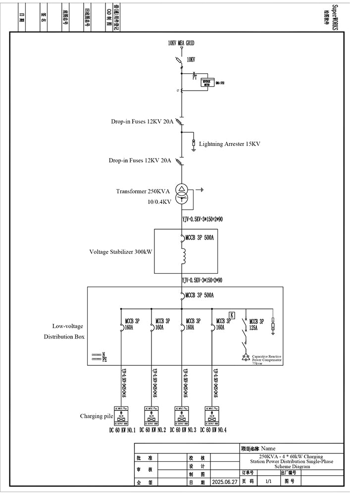
Further calculating the charging needs of the entire fleet, 50 vehicles require approximately 1250kWh of power a day. Combined with the 24 hours a day operation time, from the point of view of cost structure and operational efficiency, we provided the client with a preliminary equipment configuration plan: installing 4 sets of dual-gun 60kW ev charger with a 250kVA transformer. In addition, in view of the instability of the local power supply in Africa, we suggest the client to equip an additional voltage regulator to better protect the service life of all the power distribution equipment and ensure the stable operation of the ev charging station . We also provide the client with the diagram of the power distribution plan:
3. Charging Station Layout Planning
After clarifying the equipment configuration scheme, the first phase of charging station building program was issued for the client. The program gives full consideration to the functional partition and spatial layout of the charging stations to ensure efficient operation and good user experience of the charging stations . The specific layout is as follows:
3.1 Area A: Rechargeable Parking Spaces
Area A is the core area of the charging station site, which is mainly used for vehicle charging. We have planned 4 sets of dual-gun charging piles with 8 parking spaces, each with dimensions of about 2.5 m x 5 m, which can accommodate 8 vehicles for charging at the same time. According to the layout of the charging piles and the parking demand of vehicles, the area of Area A covers about 160~200 square meters. The design of this area takes into full consideration the convenience of vehicle access and charging efficiency, ensuring that vehicles can complete the charging process quickly and safely.
3.2 Area B: Location of Charging Piles
Area B is the area where the charging pile is installed, usually at the end of the charging parking space. To ensure that the charging piles are securely installed and safe to use, it is recommended that the charging piles be installed against a wall or centered. Depending on the size of the charging piles and the installation requirements, Area B covers an area of approximately 30 to 40 square meters. The design of this area not only meets the installation requirements of the charging piles, but also provides a convenient space for vehicle charging operations.
3.3 Area C: Power Distribution Equipment Installation Locations
Area C is the installation area for power distribution equipment, mainly used for placing critical equipment such as transformers, voltage regulators and distribution boxes. Considering the safety and maintenance convenience of these equipment, it is recommended to use fencing to isolate this area to avoid the danger of high voltage. Area C covers the area of about 30~40 square meters. The design of this area takes into full consideration the heat dissipation, maintenance and safety protection of the equipment to ensure the stable operation of the charging site.
3.4 Area D: Vehicular Access Lane
Area D is a vehicular access lane for one-way or two-way staggered vehicle traffic within the charging station site. In order to ensure smooth and safe passage of vehicles, we recommend that the width of the lanes be greater than 6 meters. The design of this area takes into account the ease of vehicle access and traffic organization within the site, avoiding vehicle congestion and the risk of collision.
3.5 Area E: Security/Control Area or Driver's Rest and Waiting Area
Area E is the auxiliary function area of the charging station, which can be used as a comprehensive area for security, control, driver rest and waiting functions. Considering the hot summer weather in Africa, it is recommended to provide drivers with resting and waiting space in this area, equipped with basic services such as drinking water facilities, in order to enhance the driver's experience. Provide a comfortable resting environment for drivers while waiting for charging.
Functional Partitioning Recommendations(efficient configuration)
| Area | Functional Description | Recommended Area | Special Note |
|---|---|---|---|
| Area A | Charging space area (8) | 160~200㎡ | Each parking space is about 2.5m×5m, which can satisfy 8 vehicles charging at the same time (double-gun charging pile) |
| Area B | Charging equipment area (4 x 60kW charging piles) | 30~40㎡ | Piles are arranged against a wall or central island, near the end of the parking space |
| Area C | Power distribution equipment area (transformers + voltage regulators + distribution boxes) | 25~40㎡ | It is recommended to arrange the equipment in separate enclosures or small equipment rooms for isolation. |
| Area D | Passing lane | ≥6 meters | Accommodate one-way vehicular circulation or staggered traffic in opposite directions |
| Area E (Optional) | Security control area/Driver's rest and waiting area | 10~20㎡ | Can be used as staff duty room, toll collection area, monitoring and control, driver's rest and waiting area |
4. Program Deepening and Quotation
After reaching a consensus with the client on the first phase of preliminary program, the two sides entered the second phase of program deepening stage. Our company provided the client with detailed quotations and lists of all station-building configurations, and further optimized them according to the client's needs and feedback.
5. Technical Support and Implementation
Due to the lack of local technical personnel, the client requested our company to send an additional technician to the local technical guidance, and bear the travel and salary costs of the technician, the two sides reached an agreement. After receiving the deposit from the client, our company issued the final layout design and construction drawings of the station for the client.
6. Summarization
Through the above detailed design and implementation process, we have successfully deployed a set of efficient, economical and reliable DC charging pile system for our African client. This case fully demonstrates our professional ability and service level in the field of charging facilities, and also provides valuable reference experience for other electric vehicle operation fleets. In the future, we will continue to provide high quality charging solutions to our global clients and promote the sustainable development of the electric vehicle industry.