
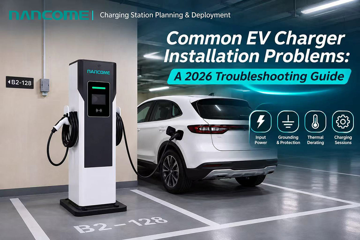
Practical diagnostics for EPC contractors, installers and charging operators: input power, grounding, protection, thermal derating, charging sessions and handover.
A charger that powers on is not necessarily ready for commercial service. Diagnose the complete site-to-vehicle system, document the evidence, and never bypass electrical safety protection.
EV Charger Installation Snapshot — 2026
EV charging deployment is scaling up while individual charging sites become more electrically demanding. The International Energy Agency reports that the global stock of public charging points exceeded 7 million at the end of 2025, up more than 33% year on year. The average rated power of public charging points was approaching 50kW as faster chargers gained share. [1]
This changes what “successful installation” means. An installer must confirm not only that a cabinet starts, but also that it delivers stable power, starts and ends real charging sessions, communicates where required, and can be serviced safely. U.S. Department of Energy guidance treats utility coordination, permits, inspection, maintenance and operating responsibilities as connected parts of infrastructure deployment. [2]
- This guide is organized by on-site symptoms and diagnostic evidence, not by generic project mistakes.
- The examples are illustrative engineering scenarios, not documented fault cases at NANCOME customer sites.
- All electrical measurements, modifications and commissioning must be carried out by qualified personnel under local codes and manufacturer instructions.
1. First Step: Separate Site, Charger, Vehicle and Service Faults
When a new station fails its first charging session, replacing a power module immediately may waste time. Start with the failure boundary: incoming power, protective devices, charger controls, charging connector, vehicle response or authorization/payment service. Record the time, equipment serial number, firmware/configuration version, alarms and conditions when the symptom appeared.
| Diagnostic layer | Typical evidence to collect | Responsible team |
|---|---|---|
| Utility / site electrical | Supply voltage, phase arrangement, upstream breaker, grounding scheme, load profile | Licensed site electrician / EPC |
| Charger equipment | Alarm history, emergency-stop state, fan status, module output, internal self-check | Manufacturer / authorized service |
| Vehicle interface | Connector fit, lock state, vehicle model, SOC, charge-request limits, session result | Installer + vehicle / charger technical teams |
| Network / transaction | Connectivity, authorization outcome, payment response, backend event records | Operator / platform integrator |
Safety boundary: de-energize and apply appropriate isolation and lockout/tagout before accessing electrical compartments. Do not defeat residual-current protection, earthing checks, interlocks, insulation monitoring or emergency-stop circuits to “make the charger work.”
2. Problem: The Charger Does Not Power On
Typical symptom: the display remains dark, the control system repeatedly restarts, or the charger reports an input-supply fault immediately after energization.
Possible causes include absent or unstable incoming power, an incorrectly configured input voltage, an open upstream protective device, a pressed emergency stop, an auxiliary-supply issue or wiring that does not match the approved single-line diagram. Three-phase systems may also be sensitive to missing phases or an incorrect phase arrangement, depending on design.
- Check the approved nameplate input range against the actual site supply and utility service conditions.
- Verify breaker status, isolation points, phase/neutral arrangement and protective-earth continuity using approved procedures.
- Compare the recorded alarm or fault code with the exact charger model and firmware documentation.
Do not assume a charger is defective until the supply and site wiring have been verified. A unit tested at the factory may still fail at a site with incorrect input conditions.
3. Problem: A Breaker or Earth-Leakage Device Trips
Typical symptom: a protective device trips at startup, during charging ramp-up or only when two chargers operate simultaneously. The pattern is useful: immediate trips and load-dependent trips may have different causes.
Possible causes include unsuitable protective-device selection, poor selectivity, a genuine fault, wiring damage, incorrect grounding arrangements, excessive simultaneous current or residual-current characteristics that do not match the installed equipment. The required RCD/GFCI or equivalent protection type depends on the charger design and local electrical rules.
- Document which device trips, its rating, trip curve and the operating stage when it trips.
- Have a qualified engineer check coordination with upstream and downstream protection and the actual input current.
- Investigate insulation, leakage and cable conditions before considering any protective-device changes.
Never increase a breaker rating, disable earth-leakage protection or substitute a different protection type without a documented engineering review.
4. Problem: Grounding, Bonding or Insulation Alarms
A grounding alarm may be caused by poor protective-earth continuity, incorrect bonding, an unsuitable site earthing system, damaged insulation or a fault in the vehicle/charger circuit. These are safety-critical conditions, not nuisance messages.
The installer should verify the site earthing design, continuity and relevant insulation-test results using the applicable procedure for the exact system. Tests must not be applied indiscriminately to connected electronics; follow the manufacturer's test limits and isolation instructions.
NANCOME's background in electrical distribution is relevant here: grounding, switchgear, protective devices and the charger must be engineered as one system rather than treated as unrelated purchases.
5. Problem: Voltage Drop, Hot Terminals or Undersized Cables
Typical symptoms include input undervoltage under load, discolored terminals, abnormal temperature rise, repeated power reduction or cable insulation stress. Cable sizing is not determined by charger kW alone: installation method, conductor material, route length, ambient temperature, grouping, permissible voltage drop and local rules all matter.
- Compare measured input voltage at no load and at the relevant charging load.
- Confirm conductor cross-section, cable routing, gland sizing, terminal type and documented tightening requirements.
- Where appropriate, use authorized thermographic or temperature checks under controlled conditions to identify abnormal hot spots.
The corrective action may involve repairing a termination, redesigning the feeder, adjusting the charging load or upgrading upstream distribution. Do not treat recurring overheating as a software problem.
6. Problem: Charging Power Is Lower Than the Nameplate
A 240kW DC fast charger does not deliver 240kW to every vehicle. Actual power depends on the vehicle's battery voltage, current request, state of charge, temperature, charging curve, connector rating, charger output limits and any site power-sharing policy.
An illustrative electrical relationship is P (kW) ≈ V (volts) × I (amps) / 1,000. At 500V and 200A, DC output is about 100kW; at 800V and the same 200A, it is about 160kW. These examples are arithmetic only: the actual vehicle and charger must both support the operating point.
| Observed behavior | What to check before declaring a fault |
|---|---|
| Power starts high, then falls | Vehicle SOC, battery temperature, normal charging curve and current request |
| Power never reaches expected level | Vehicle voltage/current limits, cable rating, charger output configuration |
| Two guns each deliver less power | Shared power-module allocation, total station cap and active load-management settings |
| Power drops in hot weather | Thermal alarms, inlet/outlet airflow, fan/filter condition and permitted derating |
For acceptance testing, record vehicle model, SOC range, battery temperature where available, DC voltage/current, charger power and elapsed time. A single peak-power screenshot is not a complete performance test.
7. Problem: Overtemperature or Thermal Derating
High-power DC charging produces heat in power modules, contactors, busbars, connectors and cables. If a cabinet derates after several minutes, investigate blocked air paths, insufficient installation clearance, filter contamination, fan faults, direct sun exposure, ambient temperature, altitude and sustained high-load duty.
- Compare site clearances and airflow direction with the model-specific installation manual.
- Confirm that adjacent cabinets, walls or protective bollards do not obstruct ventilation openings.
- Review fan alarms, internal temperature trends and whether derating is normal protection behavior.
A charger reaching rated power briefly is not the same as a station sustaining repeated sessions. This distinction becomes more important as ultra-fast public charging expands. [1]
8. Problem: Water Ingress, Condensation or Corrosion
Outdoor enclosures are exposed to rain, dust, humidity, washdown, flooding and temperature cycling. An IP54 or IP55 designation does not mean that a charger is submersible or protected against every site condition. Water can enter through improperly sealed cable glands, door gaskets, unapproved modifications or poor drainage.
Before commissioning, check cable-entry sealing, cabinet alignment, drainage direction, ground clearance and the manufacturer's weather-exposure requirements. Where a site is flood-prone, address civil design and equipment elevation rather than relying only on the enclosure IP rating.
9. Problem: Connector Locking, Cable Reach or Cable Wear
Typical symptoms include failed connector locking, a vehicle that cannot start charging, damaged pins or a cable that reaches the inlet only under tension. A cable can be electrically suitable but mechanically unsuitable for a particular parking-bay geometry.
- Verify the regional connector standard and actual target-vehicle inlet position before finalizing bay layout.
- Inspect pins, seals, locking parts, cable strain relief and gun-holster placement.
- Provide cable management that avoids sharp bends, vehicle wheel paths and standing water.
The ChargeX research program has addressed charging-system faults, connector behavior and diagnostics, reflecting the growing importance of reliable first-time charging sessions. [3]
10. Problem: The Charger Is Ready but the Session Fails
A powered-on screen and a successful network connection do not guarantee that a real charging session will begin. Possible fault layers include connector engagement, vehicle-to-charger communication, authorization, payment, transaction handling or a protection event during precharge.
The commissioning team should separate the vehicle-side charging handshake from charger-to-backend communication. OCPP support describes one interface to a management system; it does not by itself establish compatibility with every vehicle, payment terminal or third-party platform.
- Test a local or authorized start, charging energy delivery, stop command and connector release.
- Where configured, verify RFID, app/payment and remote-start flows separately, with transaction records.
- Save time-stamped charger alarms and relevant platform logs, including failures that occur only with concurrent sessions.
Research coordinated through ChargeX has shown that charge-initiation problems can sometimes be resolved through defined retry behavior; this is not a reason to ignore persistent faults or bypass required safety checks. [3, 4]
11. Problem: Multi-Charger Operation Exceeds Site Capacity
A site may pass individual charger tests yet trip upstream protection when several vehicles arrive together. Common causes include a mistaken coincidence assumption, misconfigured dynamic load management, limited transformer capacity, incorrect metering feedback or a feeder that was designed for a smaller load.
For example, four 120kW chargers have 480kW of installed DC nameplate output. The grid input requirement is higher than DC output after conversion losses, but the actual peak depends on vehicle requests and active power limits. An engineer should model the busiest realistic operating hour rather than assuming either zero diversity or an arbitrary diversity factor.
Test the planned maximum simultaneous load, power-sharing behavior and recovery after one charger disconnects. Keep a documented record of the site-wide power cap and who is authorized to change it.
12. Special Case: Installing a 220V Single-Phase DC Charger
Some commercial sites do not have a conventional 380/400V three-phase connection. NANCOME also develops floor-standing 220V single-phase DC charger options in 35kW and 42kW configurations for project-specific evaluation. However, “no 380V required” does not mean an ordinary household 220V socket is sufficient.
As a simple engineering illustration, at 220V input, 95% conversion efficiency and 0.98 power factor, a 35kW DC output would require roughly 171A of AC input; 42kW would require roughly 205A. Real design values depend on the exact model, actual voltage, efficiency, power factor, continuous duty and local code.
| Proposed configuration | Illustrative input current* | Essential site check |
|---|---|---|
| 35kW DC / 220V single-phase | About 171A | Utility/service capacity, feeder, breaker and continuous-load requirements |
| 42kW DC / 220V single-phase | About 205A | Same checks, with additional margin for site loads and operating conditions |
*Illustrative only: current = DC output power / (220V × 0.95 × 0.98). Not a product nameplate specification or installation approval.
Before ordering, submit the site electrical diagram, measured supply conditions and utility-approved capacity for model-specific review.
13. Special Case: Battery-Buffered or Mobile Charging Sites
Battery-buffered charging may help a grid-constrained or temporary site support short power peaks, but it does not eliminate energy and recharge requirements. A battery must be assessed in both kWh (usable energy) and kW (available charge/discharge power), alongside reserve SOC, recharge time, duty cycle and thermal limits.
NANCOME's mobile energy-storage charging range includes project configurations such as 65kWh with 60kW DC charging and 141kWh with 120kW DC charging. These are capacity/output pairings, not promises that full rated output can be maintained for a particular duration in every condition. Confirm the exact project configuration and available usable energy.
During site acceptance, simulate consecutive sessions and the actual battery recharge source. An isolated peak-power test cannot demonstrate a full day of operational readiness.
14. FAT, SAT and Handover: A Practical 12-Point Checklist
A structured acceptance plan reduces repeat site visits. Agree the test evidence and responsible parties before shipment, then verify the installed system against the actual project configuration.
| Stage | Checks to document | Evidence / sign-off |
|---|---|---|
| Before shipment (FAT) | 1. Model/power/connector; 2. wiring and protection; 3. functional and load tests; 4. configured features | Serial number, factory test sheet, firmware/configuration record |
| Before energization | 5. Permits/inspection; 6. feeder and earthing; 7. cable entries/clearance; 8. protection coordination | As-built single-line diagram, installation checklist, electrical test records |
| Site acceptance (SAT) | 9. Real-vehicle start/stop; 10. alarms/E-stop; 11. concurrent load; 12. network/payment where used | Signed SAT report, measured power, screenshots/logs and open-issue register |
| Handover | Operator training, maintenance plan, spare parts and escalation ownership | Manuals, warranty scope, contacts and service responsibilities |
A passed SAT should mean a usable charging service, not merely a lit display. The U.S. DOE guidance likewise emphasizes installation planning and ongoing maintenance responsibilities. [2, 5]
15. How NANCOME Supports Project-Oriented Installation
NANCOME brings more than 30 years of electrical manufacturing experience, dating to 1992, to EV charging and power-distribution projects. For B2B customers, the practical advantage is the ability to discuss the charger together with site supply, protective devices, cabinet design, thermal conditions, factory testing and commissioning documentation.
- DC fast charging: floor-standing configurations from 40kW to 480kW for public, commercial and fleet applications; connector options depend on the ordered model.
- AC charging: 7kW, 11kW and 22kW single-connector options for suitable parking and workplace applications.
- Power distribution: low-voltage switchgear and distribution cabinets to support project-specific electrical integration.
- Mobile energy storage charging: selected battery-and-charger combinations for temporary or grid-constrained projects.
- Project options: regional connectors, remote monitoring, RFID, 4G/Ethernet, OCPP 1.6J/2.0.1 support and OEM/ODM configurations, subject to the exact product specification.
For export projects, NANCOME can coordinate a model-specific pre-shipment checklist and technical review. This does not replace the local EPC contractor's responsibility for permits, code compliance, installation and site acceptance.
Explore Relevant NANCOME Products
- NANCOME DC EV Charger Range — commercial DC charging equipment and application categories
- NANCOME Energy Storage Charging Systems — mobile and battery-assisted charging options
- NANCOME Power Distribution Cabinets — electrical distribution and cabinet solutions
16. What to Send NANCOME for a Faster Technical Review
To reduce quotation revisions and commissioning risk, send the project information below before selecting a charger model:
- Project country/city, installation environment and applicable local approvals.
- Target EV brands/models, connector standard, charging-port location and expected dwell time.
- Requested charger quantity, kW per connector and expected simultaneous charging demand.
- Site input voltage, phases, frequency, transformer capacity, feeder details and known voltage instability.
- Outdoor temperature, dust/rain exposure, cable management needs and civil-layout drawings.
- Backend/payment requirements, network availability, commissioning schedule and local service arrangements.
Ready to review your site? Contact NANCOME for a project-specific EV charging solution. Include your electrical single-line diagram and vehicle list where available.
Result: Solve the Whole Charging System, Not Just the Cabinet
Common EV charger installation problems rarely have a single universal fix. A failed session may originate in the grid connection, protection design, cable route, enclosure environment, vehicle interface or site communications. A reliable project uses evidence-based diagnostics, coordinated electrical engineering, model-specific factory testing and realistic site acceptance.
For overseas EPC contractors, distributors and charging operators, NANCOME can help align charging equipment and electrical distribution choices with the actual project. The final installation must still be validated by qualified local professionals.

Leave a comment
All comments are moderated before being published.
This site is protected by hCaptcha and the hCaptcha Privacy Policy and Terms of Service apply.